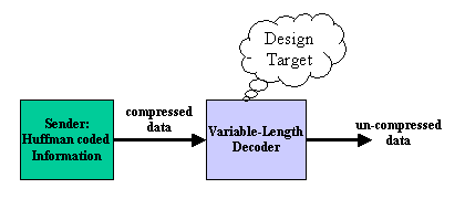
Figure1 System Diagram
Tom Wada, Prof of the University of the Ryukyus, Information Engineering Dept.
This year's design target is the Variable-Length Decoder for Huffman codes, with which the amount of the digital data is compressed. Using the decoder we can obtain the original data from the compressed data.
There are bunch of multi-media data compression algorithms such as MP3, AAC (Advanced Audio Coding) for sound and voice compression, and JPEG, MPEG for digital still / motion image compression. In those algorithms, DCT (Discrete Cosine Transform) is used with the combination of Quantizations.
In those algorithms, the Huffman code is also used in order to further decrease the amount of the data. Since the sound, voice, image compressions are frequently used in a real time application such as the broadcasting, you have to design the Variable-Length Decoder for a real time application.
Since this contest is mainly for University students, the code size in the task is relatively small to let student to design easily. In addition, some task level is prepared for several students levels. The requirements of the design is to write HDL (VHDL or Verilog HDL) and to synthesize digital circuits using Synopsys design analyzer or any other EDA tools. Making FPGA is also optional but our judges love to see your FPGA designs.

Figure1 System Diagram
The figure 1 shows the system diagram. The system is divided into two large blocks such as Sender and Decoder. The sender transmits the compressed data using Huffman codes, and the decoder uncompresses the data and recover the original data.
Since the Huffman code length is not fixed, the decoder has to find out the length of each code while processing. In the following sections, the basics of the Huffman codes are explained in order the students who has the digital design knowledge to challenge the design task.
Suppose the following example. There is a sentence in which only 5 characters A to E are used.
CEACDABABCEABADACADABABADEACBADABCADAEE
In total there are 39 characters. The table 1 show the each character's appearance frequency.
| Symbol | Frequency to appear |
| A | 15 |
| B | 7 |
| C | 6 |
| D | 6 |
| E | 5 |
Table1. Each Character's Appearance Frequency
From the table 1, you will notice the appearance frequency of 'A' is maximum. If you want to express the sentence as a digital data, you can assign fixed length bit pattern to each alphabets. Please see the table 2.
| Symbol | Frequency to appear | Bit Pattern | Total bits |
| 15 | 000 | 15*3=45 | |
| B | 7 | 001 | 7*3=21 |
| C | 6 | 010 | 6*3=18 |
| D | 6 | 011 | 6*3=18 |
| E | 5 | 100 | 5*3=15 |
| Total 117bits |
Table 2. Fixed Length Code
In order to express the 5 alphabets, 3 bits-length code is used. Since there are totally 39 alphabets, 39*3=117 bits are needed to express the sentence in digital data.
In the table 2 example used the 3 bits fixed length code. Since the appearance frequency of 'A' is high, if we use shorter length code for 'A', the amount of digital data to express the sentence can be decreased. One method to do this is to use the Huffman code. The table 3 shows the the example using the Huffman code. The total number of bits are reduced from 117 to 87 bits.
| Symbol | Frequency to appear | Huffman code | code length | Total bits |
| A | 15 | 0 | 1 | 15*1=15 |
| B | 7 | 100 | 3 | 7*3=21 |
| C | 6 | 101 | 3 | 6*3=18 |
| D | 6 | 110 | 3 | 6*3=18 |
| E | 5 | 111 | 3 | 5*3=15 |
| Total 87bits |
Table 3. Huffman Code
Using the Huffman code in tha table 3, the word 'BAD' can be expressed '1000110', which is 7 bits length. Instead, the bit stream '01100111' can be analyzed from the beginning then the word 'ADAE' can be recovered. Using the figure 2, the decoding method will be explained.
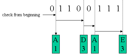
Figure 2. Huffman Code Decoding
The bit stream '01100111' has to be analyzed from the beginning, then find out a matching Huffman Code. Since the code length is not fixed, once the matched Huffman code is detected, the first bit of the next code can be found. In the example of the figure 2, at first the code '0' is found. Then you can know the alphabet 'A' and the code length of 1. Then you can restart the analysis from the second bit. After 3 more bits are analyzed, the code '110' will be found. Then you can know the alphabet 'D' and the code length of 3.
The Huffman code satisfies the condition of " any code of the group does not match the any prefix of other code of the group". Then the decoding method explained above can only generate the original data.
Suppose you are designing the part of the image data uncompression system. Figure 3 shows a one example of the black and White image data. Each pixel (picture element) is organized by 3 bits. Then there are 8 levels of the pixel intensity.
![]()
Figure 3. Black and White Image
The left figure in the figure 3 is 8 kinds of pixel intensities. The center number is the level. The most bright pixel is 0. The larger the number increases, the darker the pixel gets. Since there are 8 levels, 3 bits can express the levels. Since the right image (cross mark) is organized by 8x8=64 pixels, simply the image needs 64x3=192 bits.
The table 4 shows a example to apply the Huffman code to this image. Most frequently appeared pixel number of 0 corresponds to the code '1'. In total, the cross mark image can be expressed in 168 bits. Then the compression ration is 168/192=87.5%.
| Pixel Number | Frequency | Huffman Code | Code length |
Total bits |
| 0 (white) | 24 | 1 | 1 | 24 |
| 1 | 16 | 011 | 3 | 48 |
| 2 | 8 | 0101 | 4 | 32 |
| 3 | 2 | 0100 | 4 | 8 |
| 4 | 2 | 0011 | 4 | 8 |
| 5 | 4 | 0010 | 4 | 16 |
| 6 | 4 | 0001 | 4 | 16 |
| 7 (black) | 4 | 0000 | 4 | 16 |
| Total 168bit |
Table 4. Huffman Coded Cross Image
The table 5 shows more details of the pixel number and it's Huffman code of the cross mark.
| Pixel Number | Huffman Code | |||||||||||||||
| 7 | 0 | 0 | 0 | 0 | 0 | 0 | 7 | 0000 | 1 | 1 | 1 | 1 | 1 | 1 | 0000 | |
| 0 | 6 | 1 | 1 | 1 | 1 | 6 | 0 | 1 | 0001 | 011 | 011 | 011 | 011 | 0001 | 1 | |
| 0 | 1 | 5 | 2 | 2 | 5 | 1 | 0 | 1 | 011 | 0010 | 0101 | 0101 | 0010 | 011 | 1 | |
| 0 | 1 | 2 | 3 | 4 | 2 | 1 | 0 | 1 | 011 | 0101 | 0100 | 0011 | 0101 | 011 | 1 | |
| 0 | 1 | 2 | 4 | 3 | 2 | 1 | 0 | 1 | 011 | 0101 | 0011 | 0100 | 0101 | 011 | 1 | |
| 0 | 1 | 5 | 2 | 2 | 5 | 1 | 0 | 1 | 011 | 0010 | 0101 | 0101 | 0010 | 011 | 1 | |
| 0 | 6 | 1 | 1 | 1 | 1 | 6 | 0 | 1 | 0001 | 011 | 011 | 011 | 011 | 0001 | 1 | |
| 7 | 0 | 0 | 0 | 0 | 0 | 0 | 7 | 0000 | 1 | 1 | 1 | 1 | 1 | 1 | 0000 | |
Table 5. Pixel Number and Huffman Code of Crossmark.
You can get the huffman coded cross mark in the following link. Please check it by yourself.
Huffman Coded Crossmark: crossdata.txt
In this section, one example of the variable length decoder will be explained. Since the maximum length of the Huffman code is 4 bits, at least one data can be decoded from the 4 bits code. See the example in the table 6.
| code | Pixel Number | |
| Only one Pixel Number is decoded from 4 bits code | 0001 | 6 |
| Plural Pixel Number is decoded from 4 bits code | 1111 | 0, 0, 0, 0 |
| 1011 | 0, 1 |
Table 6. Decoding example
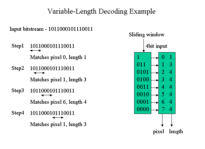
Figure 4. Algorithm Example of Variable-Length Decoder
The explanation of the algorithm in the figure 4.
STEP1:
In the algorithm, 4 bit-wide sliding window is used. The 4 bit data corresponding the sliding window is compared with the righthand side table. The top of the table is '1'. The MSB of the input 4 bits is '1' then match the top of the table in spite of the other 3 bits and outputs the pixel number of '0' and the code length of 1.
STEP2:
In the STEP1, the code length is 1. Then shift the sliding window by 1 bit then get the 4 bit inputs corresponding the new sliding window and proceed the same procedure as STEP1. In the example, the new 4 bits is '0110' then the MSB 3bits will match '011'. As a result, pixel number of 1 and the code length of 3 will be obtained.
STEP3:
In the STEP2, the code length was 3. Then shift the sliding window by 3 bits then get the next 4 bits inputs. And repeat the same operation.
In this section, the hardware organization of the algorithm described in the section 3 will be shown.
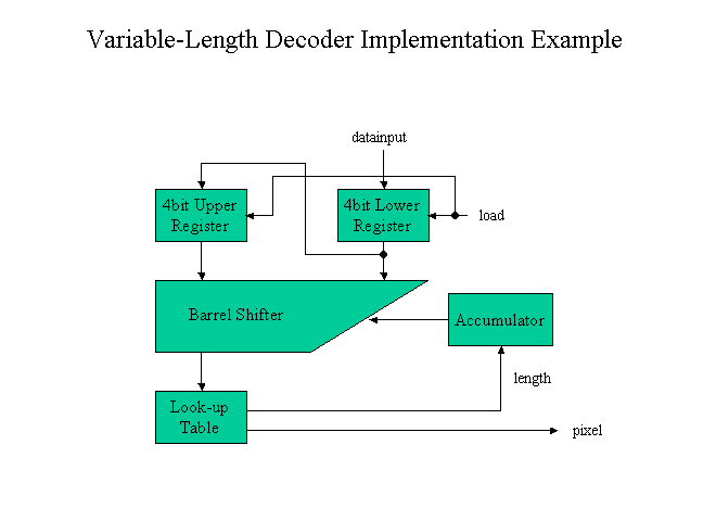
Figure 5. Architecture Example of Variable-Length Decoder
In this architecture, two sets of 4 bit registers are included. The 4 bit width sliding window will be inside of this 8 bit width. Then the 4 bit inputs corresponding the sliding window has to be compared with the Look-up table.
The look-up table outputs both the pixel number and the code length. According to the code length, sliding window has to be shifted. This shift operation is realized by the accumulator and Barrel Shifter.
The timing critical path will be Barrel Shifter -> Look-up Table -> Accumulator -> Barrel Shifter. In order to achieve the higher clock rate, circuit optimization such as pipelining will be necessary.
Figure 6 shows the total of the system including the sender and VLD (Variable-Length Decoder).
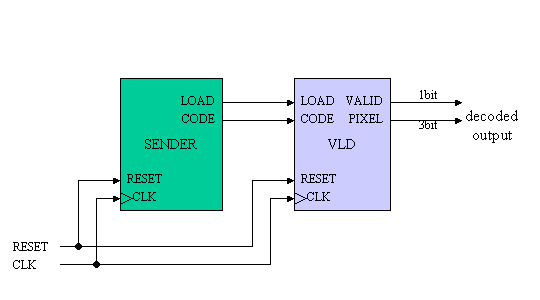
Figure 6. System Diagram
SENDER:
The SENDER outputs the Huffman coded cross image data from the CODE output. The data can be found in the following link. LOAD signal is 1 bit width and is asserted when CODE is valid.
Huffman Coded Crossmark: crossdata.txt
VLD:
VLD received the CODE signal and uncompress operation inside then outputs the decoded pixel number on PIXEL terminal. The PIXEL signal indicated the integer from 0 to 7, then 3 bit wdth signal. VALID will be asserted when the PIXEL signal is valid.
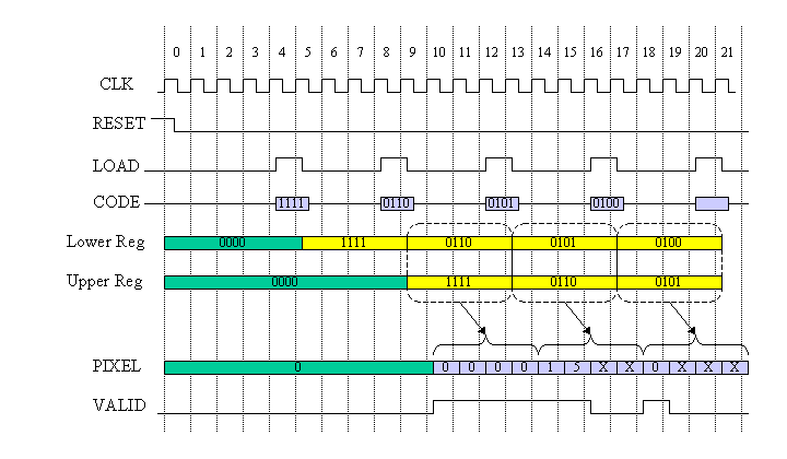
Figure 7. System Timing Diagram
Figure 7 shows the operational timing. After the dis-assertion of RESET signal, SENDER outputs CODE signal such as 1111011001010100....
In this timing diagram, the bit width of CODE signal is 4 bits. Then every 4 cycle, LOAD signal is asserted and the 4 bit width CODE is captured into the Lower register. When the following LOAD signal is asserted, the contents of the Lower register is transferred into the Upper register and the next 4 bit CODE is captured into the Lower register.
The total 8 bits of Upper and Lower register contents are analyzed from the top. Then the decoding is performed. PIXEL signal is output and VALID is asserted when the PIXEL is valid.
The decoding process will continue until all bits in the Upper register are processed. If the upper bit is found in the Upper register and some Lower register bit will be used if necessary. After all bits in the Upper register is processed, the decoding is posed and VALID signal gets '0'.
Since there will be maximum 4 PIXEL outputs from the Upper 4 bits register, CODE data is input every 4 cycles in this design.
The beginners' task has the following pin lists.
|
VLD |
|||
| signal name | in or out | bit width | explanation |
| CLK | IN | 1 | clock input |
| RESET | IN | 1 | assertion '1' means reset |
| CODE | IN | 4 | Huffman Code input |
| LOAD | IN | 1 | Load signal |
| PIXEL | OUT | 3 | Decoded PIXEL number output |
| VALID | OUT | 1 | PIXEL output VALID |
Table 7. Pin list for LEVEL1
SENDER and TESTBENCH VHDL file is linked as follow. Please use as it is or modified.
SENDER: sender.vhd
TESTBENCH: test_vld.vhd
In the Level 2 task, you do NOT need to follow the detail design spec.
Mandatory rule is
1) Please design decoder which can decode the crossdata.txt.
2) Any Architecture, any timing, any pin list are acceptable. I believe you can enjoy your originality.
Since it is impossible to use the same synthesis library for various participants, use the 1 exor gate delay as a unit for speed comparison.
In the previous example, total delay = 7.17 ns and 6 circuit stages, then the 7.17/6= 1.195 ns is the unit of the speed. Please normalize your circuit speed by this unit.
| Title page | 1 | Team name, Members Name, School, Grade |
| 2 | Address, Phone, Email-address | |
| 3 | T-shirt size for all members in the team | |
| 4 | Which level of task is designed. | |
| Contents | 1 | Circuit block or architecture description |
| 2 | Designed circuit functional explanation, etc. | |
| 3 | Appealing point and originality | |
| 4 | Critical path speed, and circuit area | |
| 5 | HDL codes (VHDL or Verilog HDL) | |
| 6 | Simulation waveform indicating the design is operating! | |
| 7 | Anything you want to claim |
Report has to be emailed to the following address. Please use PDF file format.
If you want to send the report data other than PDF, please consult me.
ENJOY HDL! We want to see you at OKINAWA!